3.0 Modem Router Suppliers – Fiber Node Transponder, SA120IE – MoreLink
Short Description:
Product Detail
Product Tags
Related Video
Feedback (2)
3.0 Modem Router Suppliers – Fiber Node Transponder, SA120IE – MoreLink Detail:
Cable Modem Features
▶DOCSIS/EURODOCSIS 1.1/2.0/3.0, Channel bonding: 8*4
▶Two MCX (Female) connectors for Downstream and Upstream
▶Provide two-Port Giga Ethernet MDI Signals to target board (Digital Board) through J1 & J2
▶Get DC Power Supply from Target Board by use of J2
▶Standalone External Watchdog
▶Temperature sensor on board
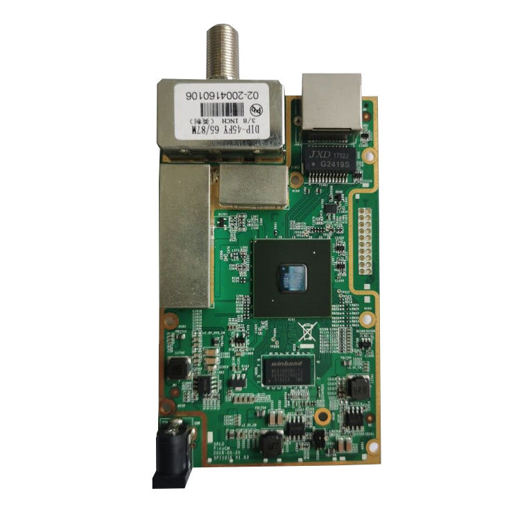
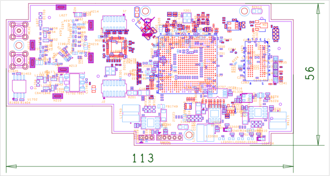
▶Small size (dimensions): 113mm x 56mm
▶Accurate RF power level 2dB at all temperature range
▶FBC for Spectrum Analyzer, integrated Splendidtel Spectrum Analyzer (SSA)
▶Support Low Power Mode and Full Function Mode Switchable
SW Features
▶DOCSIS®/Euro-DOCSIS® HFC environment auto detection
▶UART/I2C/SPI/GPIO driver customization for various devices monitoring. Such as Fiber node, Power Supply, RF Amplifier
▶Docsis MIBs / Any other customized MIB support
▶Open system API and data structure for 3rd party application’s access
▶Low power signal detection. Signal lower than -40dBmV will be represented with built-in Spectrum Analyzer
▶CM MIB Files are open for customers
▶CM management Web GUI is available on WAN or LAN
▶MSO can reboot the CM remotely via Telnet or SNMP
▶Switchable between Bridge and Router mode
▶Supports DOCSIS device upgrade MIB
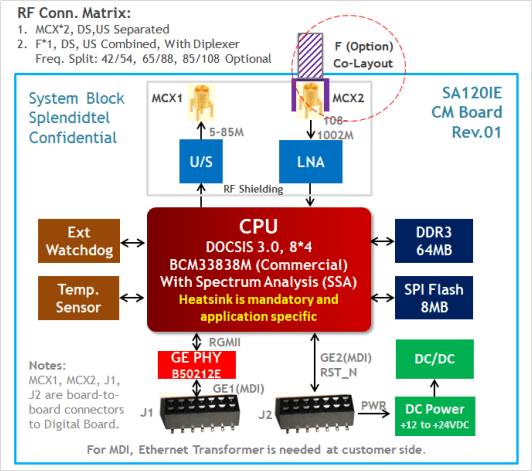
System Block
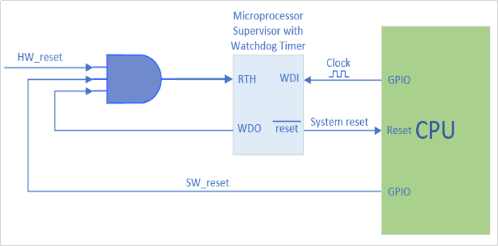
External Watchdog
An external watchdog is used to make sure the system’s operation reliably. Watchdog is kicked by the
Firmware every once in a while, so that the CM does not reset. If there’s something wrong with the CM
Firmware, then after a certain period (watchdog time), the CM will reset automatically.
Technical Parameters
| Protocol Support | ||
| ◆ DOCSIS/EuroDOCSIS 1.1/2.0/3.0◆ SNMP v1/v2/v3◆ TR069 | ||
| Connectivity | ||
| RF: MCX1, MCX2 | Two MCX Female, 75 OHM, Straight Angle, DIP | |
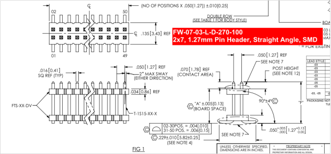
| Ethernet Signal/PWR: J1, J2 | 1.27mm 2×17 PCB Stack, Straight Angle, SMD2xGiga Ethernet Ports | |
| RF Downstream | ||
| Frequency (edge-to-edge) | ◆ 88~1002 MHz (DOCSIS)◆ 108~1002 MHz (EuroDOCSIS) | |
| Channel Bandwidth | ◆ 6 MHz (DOCSIS)◆ 8 MHz (EuroDOCSIS)◆ 6/8 MHz (Auto Detection, Hybrid Mode) | |
| Modulation | 64QAM, 256QAM | |
| Data Rate | Up to 400 Mbps by 8 Channel bonding | |
| Signal Level | Docsis: -15 to +15 dBmVEuro Docsis: -17 to +13 dBmV (64QAM); -13 to +17 dBmV (256QAM) | |
| RF Upstream | ||
| Frequency Range | ◆ 5~42 MHz (DOCSIS)◆ 5~65 MHz (EuroDOCSIS)◆ 5~85 MHz (Optional) | |
| Modulation | TDMA: QPSK,8QAM,16QAM,32QAM,64QAMS-CDMA: QPSK,8QAM,16QAM,32QAM,64QAM,128QAM | |
| Data Rate | Up to 108 Mbps by 4 Channel Bonding | |
| RF Output Level | TDMA (32/64 QAM): +17 ~ +57 dBmVTDMA (8/16 QAM): +17 ~ +58 dBmVTDMA (QPSK): +17 ~ +61 dBmVS-CDMA: +17 ~ +56 dBmV | |
| Networking | ||
| Network protocol | IP/TCP/UDP/ARP/ICMP/DHCP/TFTP/SNMP/HTTP/TR069/VPN (L2 and L3) | |
| Routing | DNS / DHCP server / RIP I and II | |
| Internet Sharing | NAT / NAPT / DHCP server / DNS | |
| SNMP version | SNMP v1/v2/v3 | |
| DHCP server | Built-in DHCP server to distribute IP address to CPE by CM’s Ethernet port | |
| DCHP client | CM automatically gets IP and DNS server address from MSO DHCP server | |
| Mechanical | ||
| Dimensions | 56mm (W) x 113mm (L) | |
| Environmental | ||
| Power Input | Support wide power input: +12V to +24V DC | |
| Power Consumption | 12W (Max.)7W (TPY.) | |
| Operating Temperature | Commercial: 0 ~ +70 oC Industrial: -40 ~ +85 oC | |
| Operating Humidity | 10~90% (Non Condensing) | |
| Storage Temperature | -40 ~ +85 oC | |
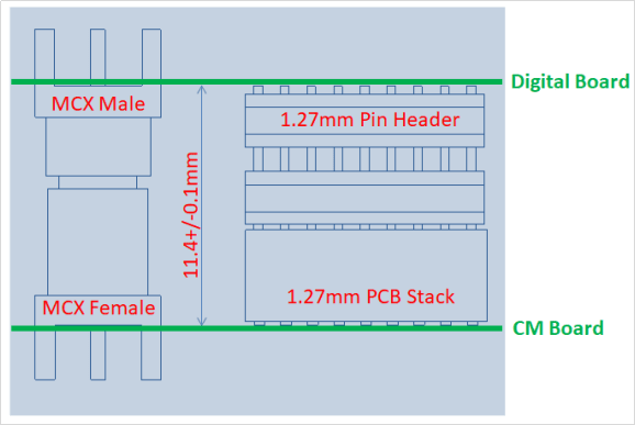
Board-to-Board Connectors between Digital and CM Board
There’re two boards: Digital board and CM Board, which use four pairs of board-to-board connectors to transmit RF signals, Digital signals and power.
Two pairs of MCX connectors used for DOCSIS Downstream and Upstream RF Signals. Two pairs of Pin Header/PCB Socket used for Digital Signals and Power. CM board is placed under the Digital Board. CM’s CPU is contacted to the housing through thermal pad to transfer the heat away from CPU and towards the housing and environment.
The mated height between two boards is 11.4+/-0.1mm.
Here’s the illustration of matched board-to-board connection:
Note:
Cause of Board-to-Board design for two PCBA Boards, in order to make sure stable and reliable connection, therefore, when
To design the Housing, it should be taken the assembly engineering and screws for fix into consideration.
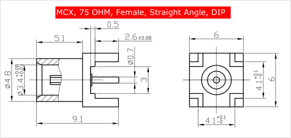
MCX1, MCX2: 75 OHM, Female, Straight Angle, DIP
MCX1: DS
MCX2: US
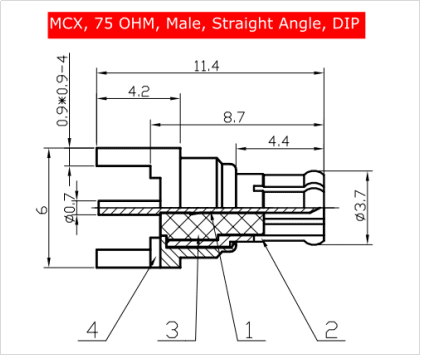
Matched MCX Male: 75 OHM, Male, Straight Angle, DIP
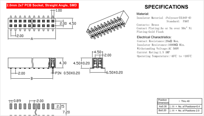
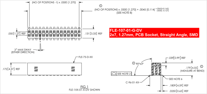
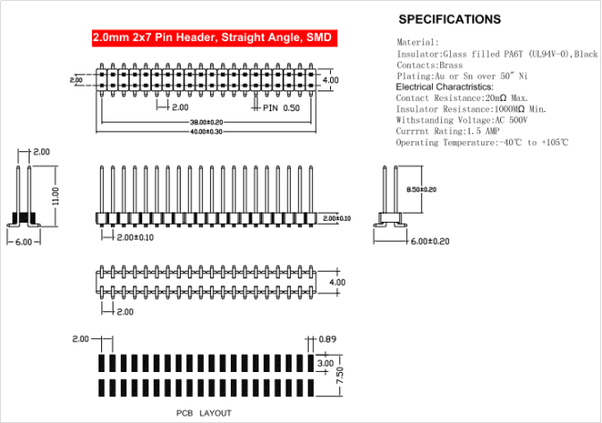
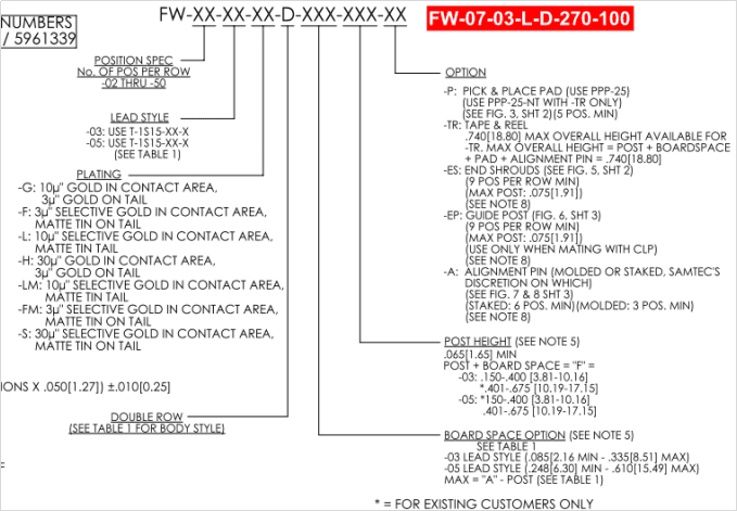
J1, J2: 2.0mm 2×7 PCB Socket, Straight Angle, SMD
J1: Pin Definition (Preliminary)
|
J1 Pin |
CM Board |
Digital Board |
Comments |
|
1 |
GND |
||
|
2 |
GND |
||
|
3 |
TR1+ |
Giga Ethernet Signals from CM board. There’s NO Ethernet transformer on the CM board, here’re Only the Ethernet MDI Signals to Digital Board. RJ45 and Ethernet transformer are placed at Digital Board. |
|
|
4 |
TR1- |
||
|
5 |
TR2+ |
||
|
6 |
TR2- |
||
|
7 |
TR3+ |
||
|
8 |
TR3- |
||
|
9 |
TR4+ |
||
|
10 |
TR4- |
||
|
11 |
GND |
||
|
12 |
GND |
||
|
13 |
GND |
Digital board provides Power to CM board, the power level range is; +12 to +24V DC | |
|
14 |
GND |
J2: Pin Definition (Preliminary)
|
J2 Pin |
CM Board |
Digital Board |
Comments |
|
1 |
GND |
||
|
2 |
Reset |
Digital board can send a reset signal to CM board, then to reset the CM. 0 ~ 3.3VDC | |
|
3 |
GPIO_01 |
0 ~ 3.3VDC | |
|
4 |
GPIO_02 |
0 ~ 3.3VDC | |
|
5 |
UART Enable |
0 ~ 3.3VDC | |
|
6 |
UART Transmit |
0 ~ 3.3VDC | |
|
7 |
UART Receive |
0 ~ 3.3VDC | |
|
8 |
GND |
||
|
9 |
GND |
0 ~ 3.3VDC | |
|
10 |
SPI MOSI |
0 ~ 3.3VDC | |
|
11 |
SPI CLOCK |
0 ~ 3.3VDC | |
|
12 |
SPI MISO |
0 ~ 3.3VDC | |
|
13 |
SPI Chip Select 1 |
0 ~ 3.3VDC | |
|
14 |
GND |
PCB Dimension
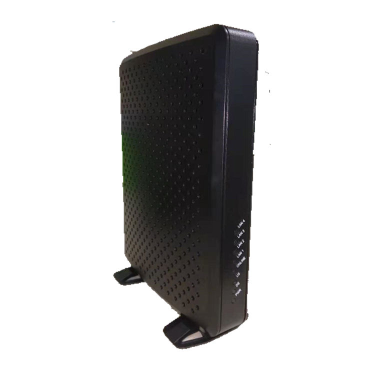
Product detail pictures:

Related Product Guide:
Our firm since its inception, normally regards item top quality as company life, constantly make improvements to generation technology, improve product excellent and repeatedly strengthen organization total good quality management, in strict accordance with the national standard ISO 9001:2000 for 3.0 Modem Router Suppliers – Fiber Node Transponder, SA120IE – MoreLink, The product will supply to all over the world, such as: Angola, South Korea, Lisbon, Corporate goal: Customers' satisfaction is our goal, and sincerely hope to establish long-terms stable cooperative relations with customers to jointly develop the market. Building brilliant tomorrow together!Our company regards "reasonable prices, efficient production time and good after-sales service" as our tenet. We hope to cooperate with more customers for mutual development and benefits. We welcome potential buyers to contact us.
This manufacturer can keep improving and perfecting products and service, it is in line with the rules of market competition, a competitive company.